The accelerator facility around the Bonn isochronous cyclotron includes the cyclotron itself, but also the two external ECR sources with the transport beamline to the cyclotron as well as the high-energy beamline and the adjoining experimental sites.
Individual components and experimental sites of the accelerator facility on the map are linked accordingly.
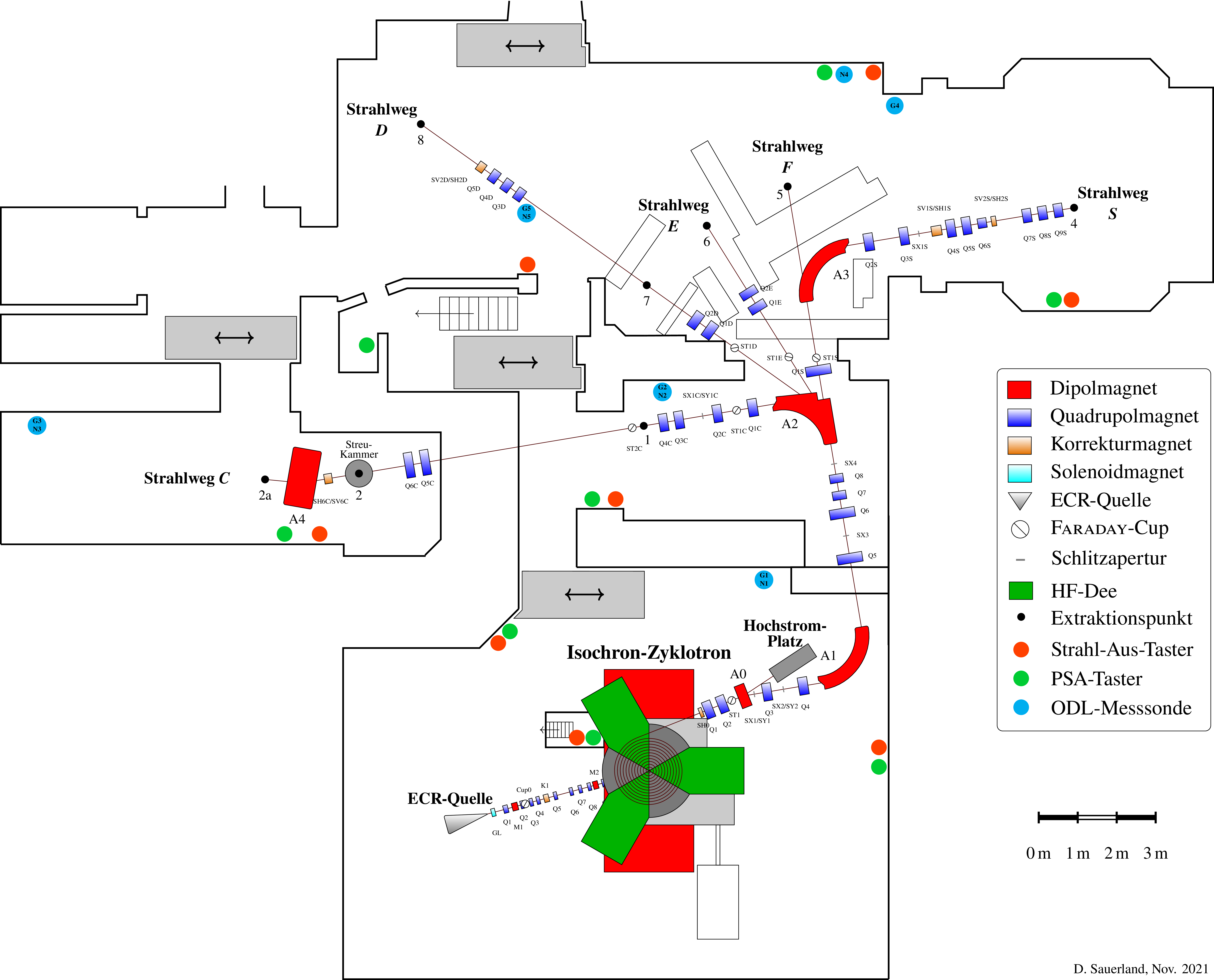
Overview of the accelerator facility of the Bonn isochronous cyclotron on the 2nd underground level in the "C-Haus" of the HISKP. The facility comprises a total of eight extraction sites in the C-, D-, E-, F- and S-ways as well as a separate high-current site for the production of radioactive probes.
ECR: Electron Cyclotron Resonance; RF: Radio Frequency; LDR: Local Dose Rate; PSS: Personell Safety System; Status: November 2021
Basics of Particle Acceleration in a Cyclotron
The principle of the cyclotron was developed in 1932 by the American physicist Ernest Orlando Lawrence (1901-1958) at Berkeley National Laboratory in the USA.
It is used to accelerate positive ions, such as protons, deuterons and \(\alpha\) particles in a vacuum chamber, where they are deflected onto a circular trajectory by a constant magnetic field and accelerated by electric fields.
Principle of Particle Acceleration
The ions are injected into the accelerating sectors, the 'Dees', in the centre of the accelerator.
Originally, these components were D-shaped, therefore they were named 'Dee'.
A high-frequency alternating voltage is applied to these dees, which generates an alternating electric field in the gap between the dees.
A positively charged ion is accelerated in this gap to the respective negative side.
Outside the gap of the dees, the ions are only affected by the magnetic field, which forces them into a circular path.
If the ions pass a Dee at the peak of the accelerating voltage, they gain energy in the gaps and consequently continue to propagate on a circular trajectory with a larger radius.
Once the ions with increasing energy have reached the outer radius of the accelerator on their spiral trajectory, they are deflected out of the cyclotron by an electrostatic deflection electrode (deflector).
The Classic Cyclotron
In the magnetic field \(B\), a particle of mass \(m\), charge \(q\) and velocity \(v\) moves on a circular trajectory with radius \(r\).
From the equality of centripetal and Lortentz force,
$$\underbrace{\frac{m \cdot v^2}{r}}_{\text{centripetal force}}~~ =~~~~~ \underbrace{q \cdot v \cdot B}_{\text{Lorentz force}}~\text{,} $$
the velocity \(v=2\pi r \cdot \nu_0\) gives the cyclotron resonance condition to be
$$\frac{m}{q} = \frac{B}{2 \pi \nu_0} .$$
Here, \(\nu_0\) is the number of revolutions of the particles per second, the revolution frequency.
To ensure that the particles always arrive in the gaps of the dees at the time when the alternating voltage accelerates the particles (the positive half-wave of the alternating voltage accelerates while the negative half-wave decelerates), the field must oscillate with a frequency \(\nu_\text{rf}\) which satisfies the isochronism condition
$$ \nu_\text{rf}= h \cdot \nu_0 ~~\text{.}$$
The frequency of the alternating voltage must therefore always be an integer multiple \(h\) of the revolution frequency.
\(h\) is called harmonic number of cyclotron's operation mode.
If, for example, only one dee is used for particle acceleration in the cyclotron, \(h=1\) is typical. In a cyclotron with three Dees at an angle of 120° to each other, \(h=3, 6\) or \(9\) is also possible.
Since the alternating voltage between the gaps of the dees sometimes accelerates and sometimes decelerates, no particle beam with a time-constant current can be provided, but only a beam consisting of particle packets, so-called bunches.
The choice of \(h\) therefore also directly indicates how many bunches are present in the cyclotron per revolution.
The Isochronous Cyclotron
With the kinetic energy \(E_\text{kin}\) the magnetic stiffness of the beam increases with the particle momentum
$$ p = \beta \gamma \cdot m c $$
and deviates from the non-relativistic momentum (\(m \cdot \beta c= m \cdot v\)).
Here , \(\beta= v/c\) is the particle velocity in fractions of the speed of light \(c\) and \(\gamma\) is the relativistic Lorentz factor
$$ \gamma = \frac{m c^2 + E_\text{kin}}{m c^2} $$
which changes for protons (\(mc^2\approx 938~\text{MeV}\)) from 1 to about 1.015 during acceleration to 14 MeV.
With a radially constant magnetic field strength, this increase in momentum would lead to a reduction in the revolution frequency with the increase in energy and thus would violate the isochronous condition for particle acceleration.
Therefore, in an isochronous cyclotron, the shape of the magnet yoke is chosen so that the magnetic field also increases radially with the particles' \(\gamma\).
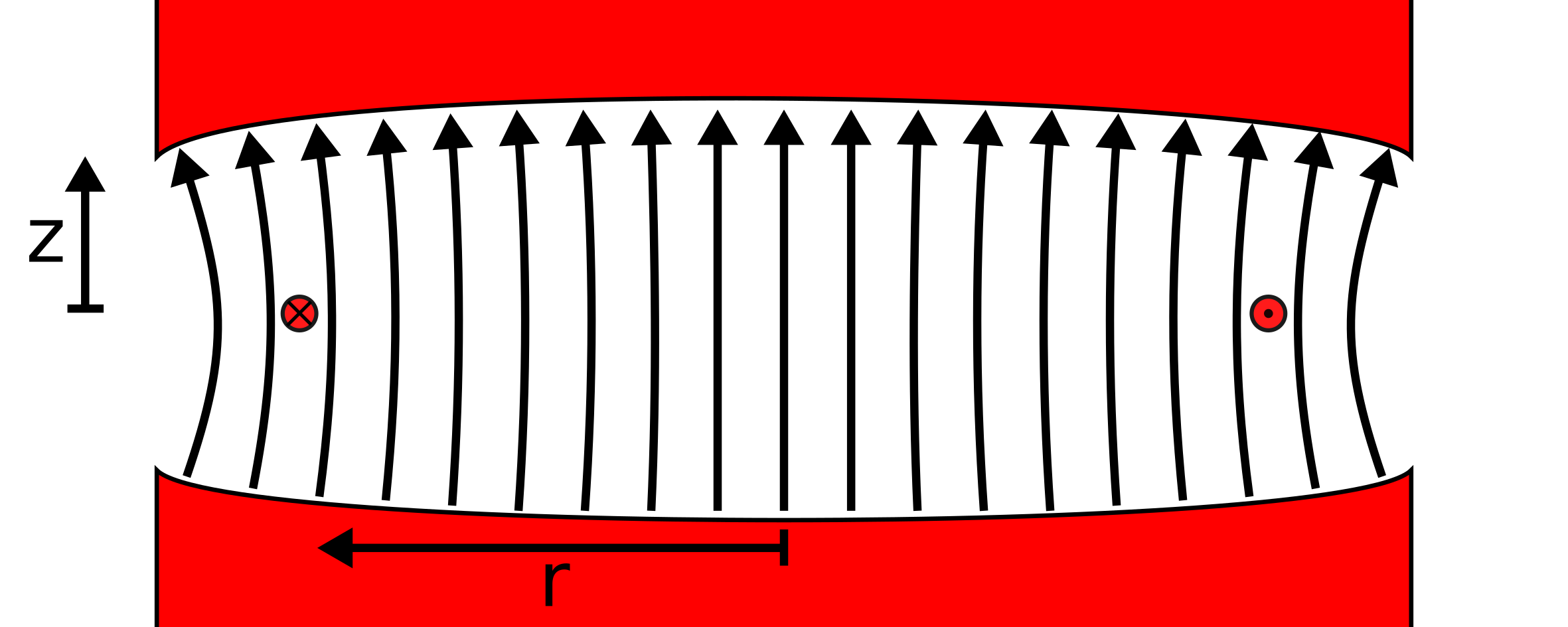
The shape of the magnet yoke (red) of an isochronous cyclotron in which the magnetic field strength increases radially.
The field lines of the magnetic field are shown as arrows. The orbit of a positive ion with the radius \(r\) are shown as red dots. Dotted or crossed circles describe the direction of movement out of or into the plane of representation.
Thus, the revolution frequency is kept constant and the isochronous condition remains fulfilled for all revolutions of the beam.
Due to the orientation of the magnetic field lines, a defocusing force acts on particles that have a vertical deviation \(z\) from the nominal path, which is why "strong focusing" is achieved by an azimuthally varying magnetic field (AVF for short, also called Thomas focusing).
This azimuthal variation of the magnetic field strength is achieved by dividing the magnet yoke into sectors of high magnetic field strength, i.e. small yoke gap, and sectors of low field strength, i.e. large yoke gap.
Due to the shape of the magnet yoke, this is also called the "hill-and-valley" pole shape.
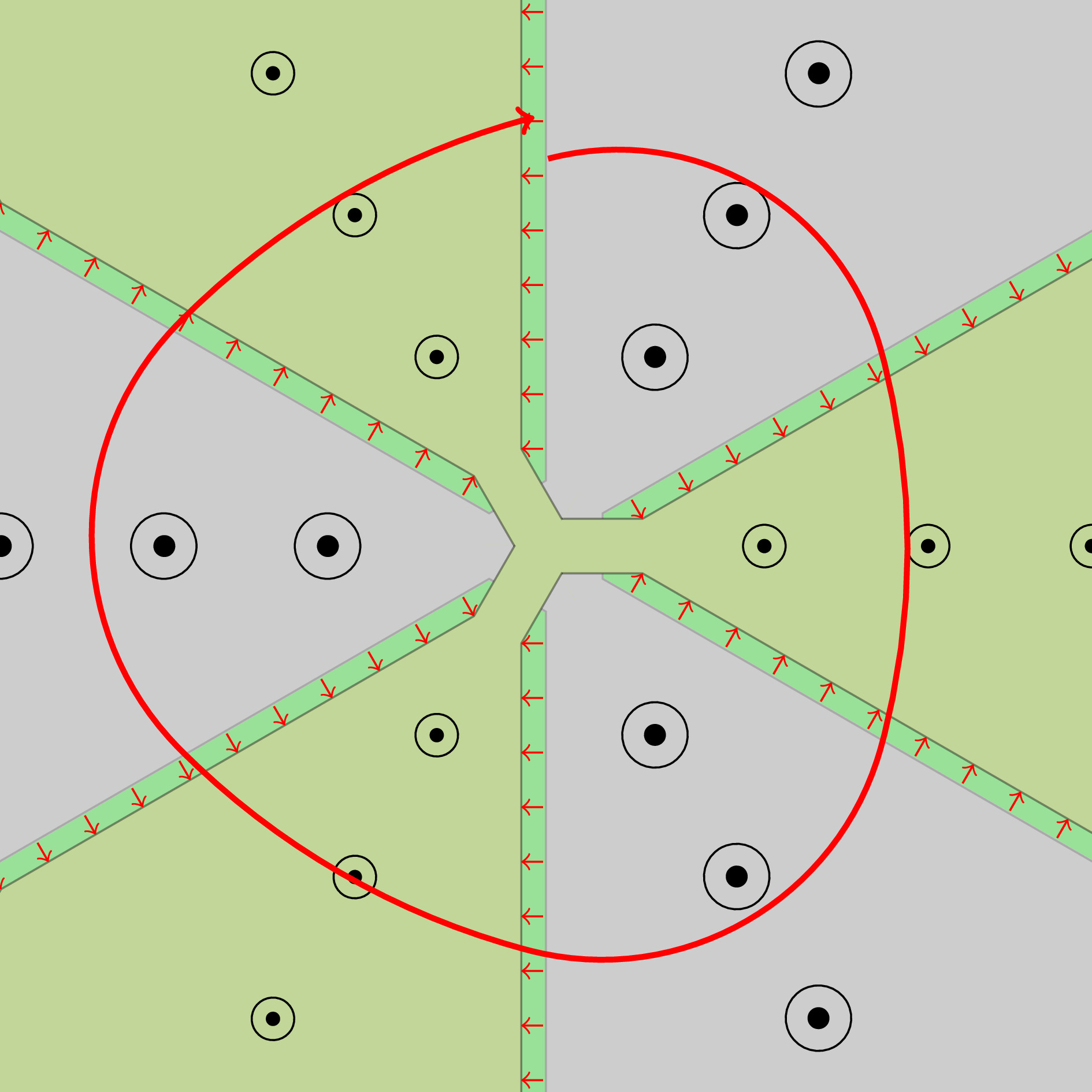
Representation of the geometric centre of an AVF isochronous cyclotron with six "hill-and-valley" sectors with three dees.
The magnetic field strength is visualised by the size of the circles; the field lines are oriented in a way that they emerge vertically out of the plane.
The three Dees are visualised in the green sectors.
The small red arrows between the inner and outer conductors of the Dees visualise the alternating voltage with which the beam particles are accelerated there.
In red, one orbit of a beam of positively charged ions is shown as an example.
Magnetic edge fields with non-perpendicular orientation form between sectors of high and low field strength.
Due to the different deflection radii in the sectors of high and low magnetic field strength, the particle beam does not enter these edge fields perpendicularly and a focusing force arises in the vertical plane, which keeps the beam on its set trajectory.
The Bonn Isochronous Cyclotron
In operation mode with \(h=3\), the Bonn Isochronous Cyclotron accelerates protons, deuterons, alpha particles and other ions with \(Q/A \geq 1/2\) to relativistic kinetic energies in the range of 7 to 14 MeV per nucleon. Heavier ions up to \(^{12}\text{C}^{4+}\) with \(Q/A \geq 1/3 \) to energies of \(E_\text{max}= 60 \cdot Q^2/A\) MeV. Here, \(Q\) is the charge and \(A\) is the mass number of the particular beam ions.
The ions are provided by one of two external electron cyclotron resonance (ECR) sources.
Depending on the ECR source used, a polarised or non-polarised particle beam can be injected from below into the cyclotron and accelerated.
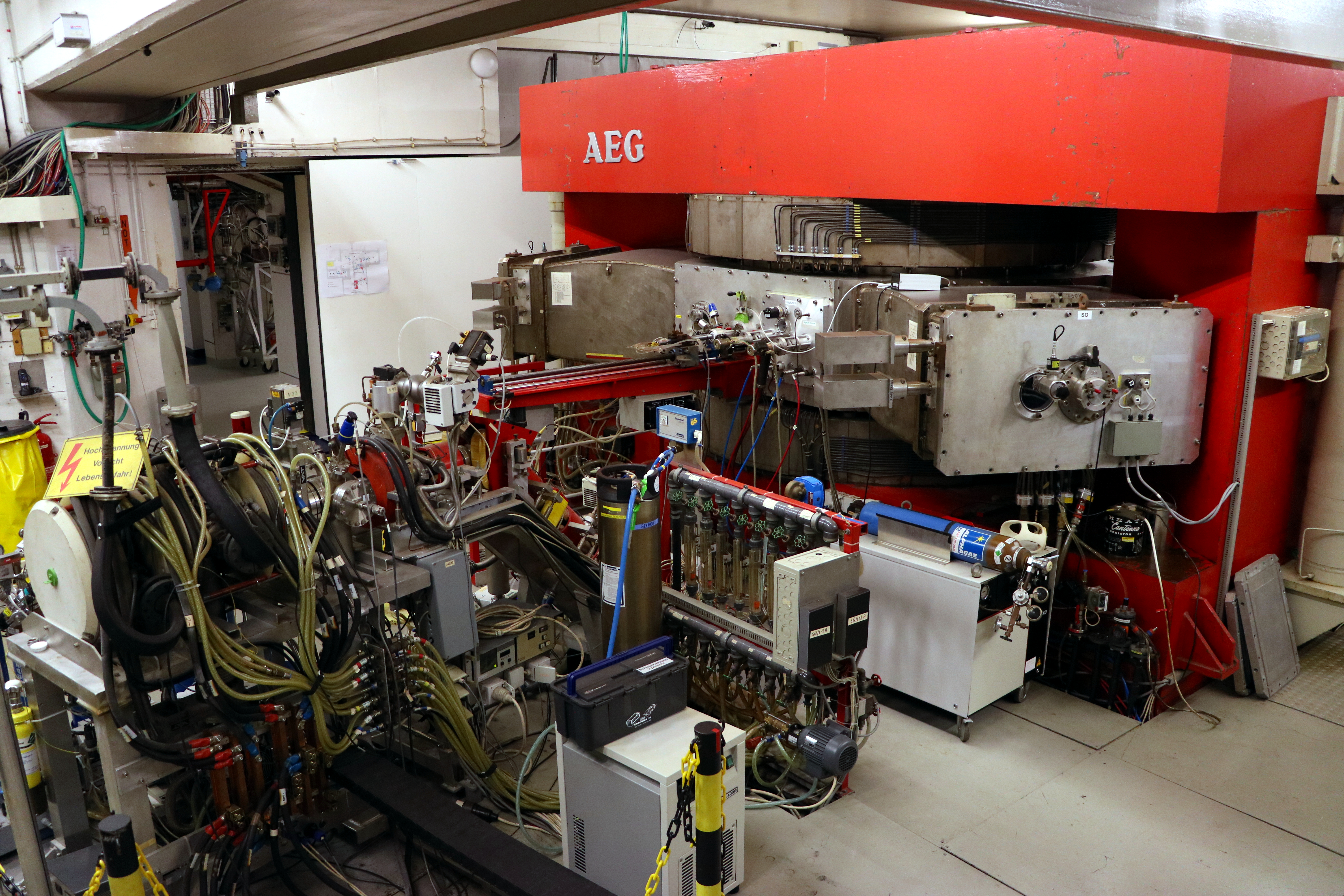
The Bonn Isochronous Cyclotron with the red main magnet with visable south-east and south-west dee and the external ECR source (left).
History
The Bonn isochronous cyclotron was built between 1968 and 1970 by AEG-Beschleunigerbau, Grosswelzheim, as the third machine of this kind after Karlsruhe and Jülich.
The magnetic yoke (approx. 250 t) of the synchro-cyclotron, which had been in operation since the mid-1950s, was modified and reused.
On 20 December 1968, the accelerator delivered the first internal deuteron beam and was handed over to the University of Bonn on 29 October 1970.
Immediately after commissioning of the cyclotron, work began on the construction of the beam guidance system in collaboration with AEG. The design of the system was aimed at fully exploiting the specific advantages of an energy-variable isochronous cyclotron with high beam quality and guiding the beam from the cyclotron to the individual beam sites (targets).
The most important work on the beam guidance system was completed by the end of 1973.
From April 1975, the cyclotron was equipped with an injection channel for external ions through the lower pole shoe and switched from internal to external ion sources. A two-stage 5 GHz electron cyclotron resonance (ECR) source and a source for polarised ions with a 2.5 GHz ECR ioniser can now be operated.
Continuous improvements have been and are being made to the accelerator system, the high-frequency generator, the control electronics, the ion sources and the recooling system to ensure and improve the function and operational safety of the accelerator.
Injection
The particle beam with a kinetic energy of 4 to 8 keV from one of the two ECR sources is injected via the low-energy beamline from below the cyclotron into its magnetic centre.
Here, the velocity of the beam particles is temporally modulated by two bunkers before injection, thus forming bunches to increase the transfer efficiency of the cyclotron from about 10% to 25 to 30%.
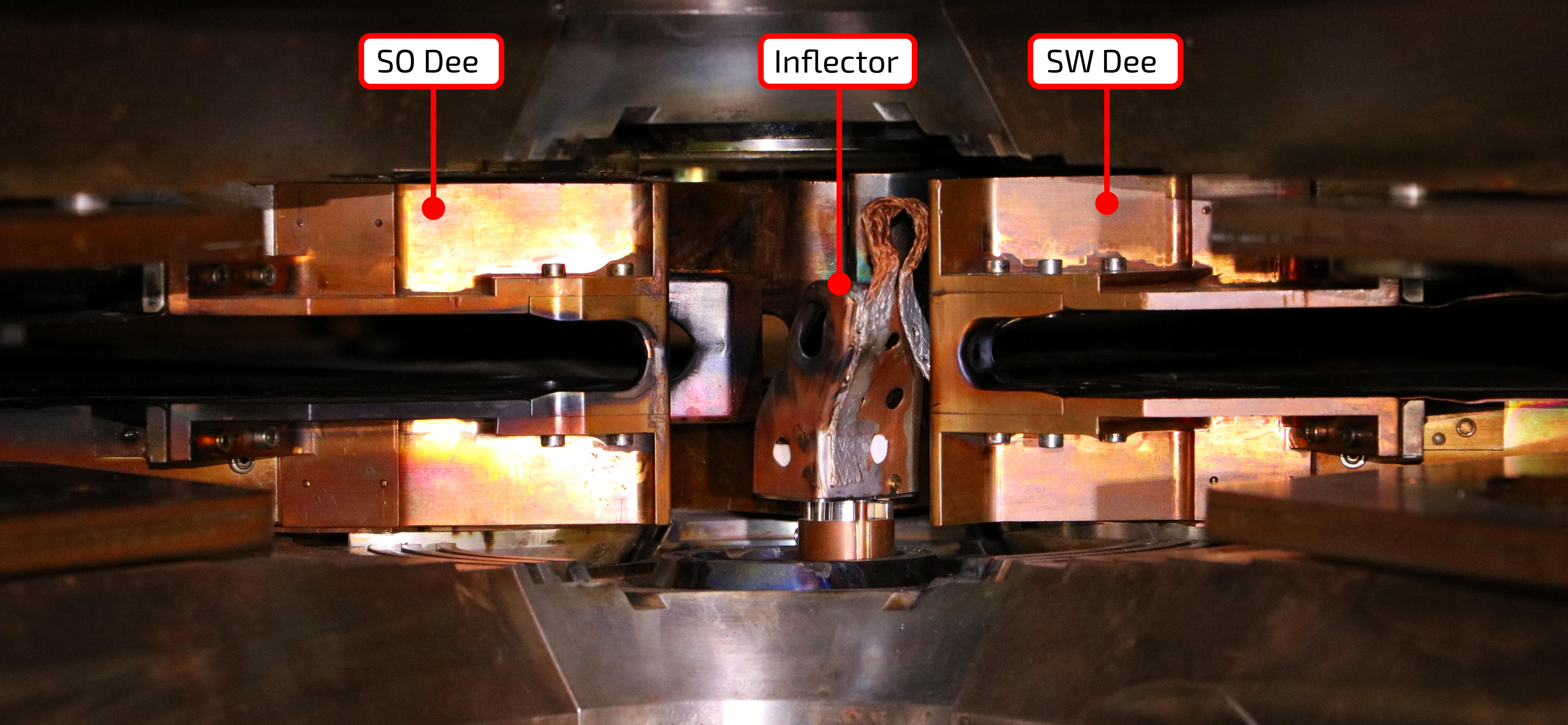
Using an electrostatic hyperboloid inflector, the direction of movement of the beam is rotated from the vertical to the horizontal plane and the beam is injected on a trajectory with a radius of about 37 mm.
View on the centre of the isochronous cyclotron without north dee.
To the left and right, the tip of the south-east and south-west dees are visible. In the centre the hyperbolic inflector can be seen.
Cyclotron Magnet
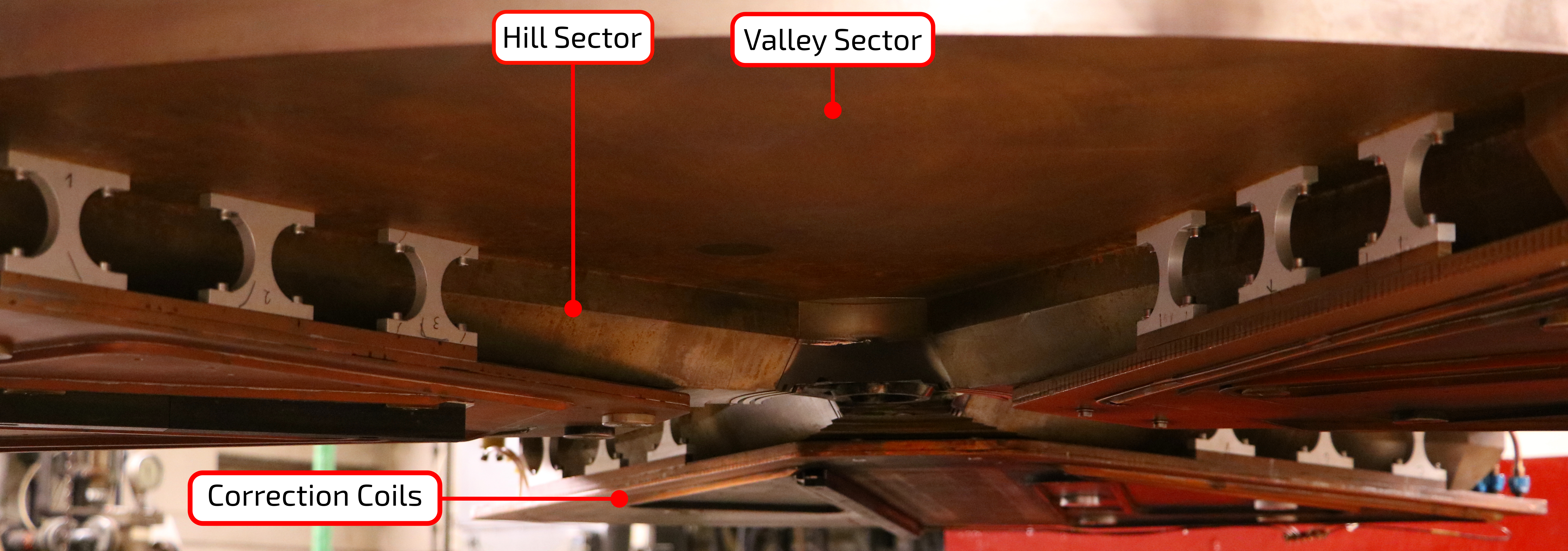
To realise the strong focusing in the vertical plane by means of AVF, the magnet's yoke is divided azimuthally into 6 sectors with alternating high and low magnetic field strength.
A " hill " sector, an area of high field strength of maximum 1.9 T, has a share of 40° to the full circle, whereas a " valley " sector, an area of low field strength of maximum 0.7 T, has a share of about 80°.
The points of symmetry of the individual hill and valley sectors have an angular distance of 120° to each other.
For local variation of the magnetic field strength of the cyclotron magnet to optimise injection and transfer efficiency, 21 pairs of partly overlapping correction coils are installed at the hill sectors.
The upper iron yoke of the cyclotron magnet in the open position.
The hill and valley sectors of the iron yoke can be seen, as well as the correction coils installed at the hill sectors.
RF System
The isochronous cyclotron operates at harmonic number \(h=3\) by default and is capable of accelerating a variety of ion species to different beam energies.
This results in the necessity of using a broadband rf system that operates at frequencies between 20 and 29.9 MHz.
Here, the initial rf signal is generated by a pulse circuit that can be adjusted in a wide frequency range and its amplitude is increased by a broadband valve tube amplifier to a rf power of up to 50 kW.
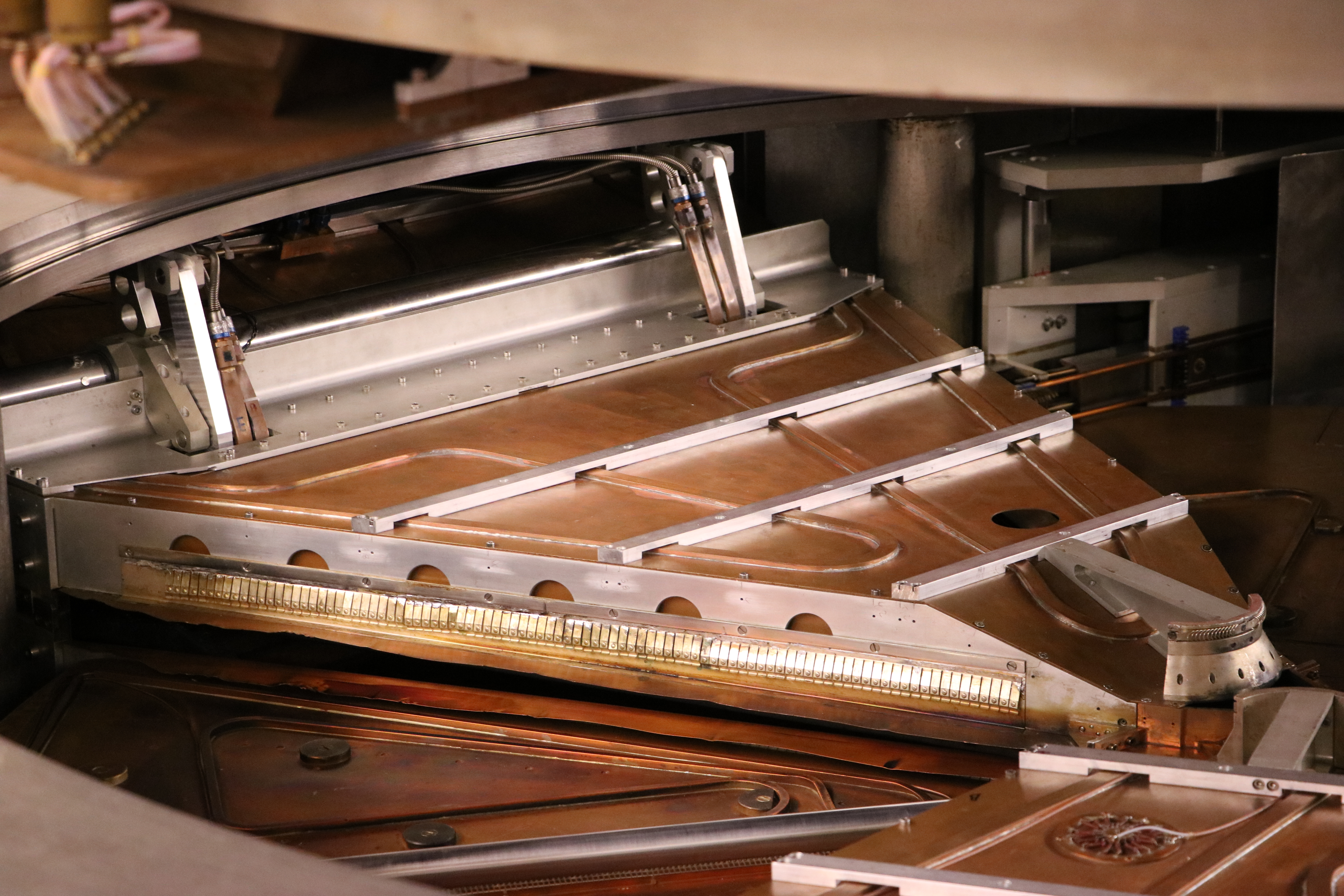
This rf signal is coupled into the north dee and transmitted via the central point to the south-east and south-west dee.
The alternating field, which forms between the outer and inner conductors of the dees in two gaps per dee and accelerates the passing beam particles, has a maximum field strength of 40 kV.
The north dee of the Bonn Isochronous Cyclotron.
Beam Extraction
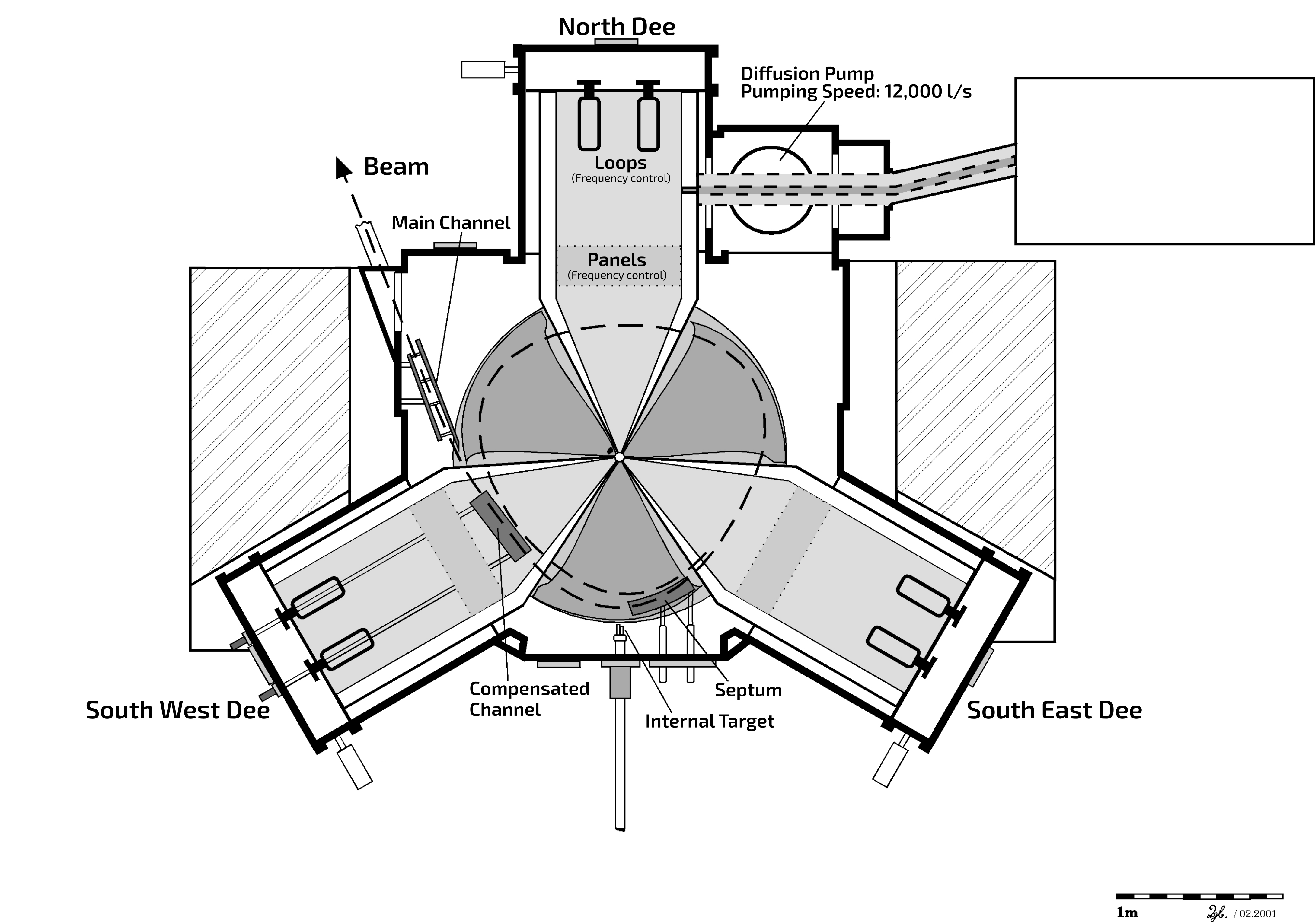
In order to realise a spatial separation of the outermost orbit (radius 900 mm) from the neighbouring orbit for the extraction of the ion beam, an electrostatic septum is used as a deflector.
The beam deflected in this way then passes through the so-called compensated channel, in which the field of the cyclotron magnet is compensated by a counter field, with an almost straight trajectory and reaches the main channel where it propagates further to the high-energy beamline.
Horizontal cut through the Bonn Isochronous Cyclotron.
Specifications of the Bonn Isochronous Cyclotron
The specifications of the Bonn Isochronous Cyclotron are listed below, sorted by individual functional groups.
Magnet
Specification of the cyclotron magnet.
Weight of the cyclotron magnet
approx. 250 t
Diameter of the pole piece
2000 mm
Number of hill sectors
3
Angle of a hill sector
40°
Spiral angle of a hill sector
0°
Gap width in hill sector / valley sector
84 / 240 mm
Width of free gap
48 mm
Average magnetic flux density
max. 1.3 T
Magnetic flux density in a hill sector
max. 1.9 T
Magnetic flux density in a valley sector
max. 0.7 T
Flutter
0.62
Number of cyclotron magnet coils
2
Magnet current / power supply output
max. 430 A / max. 38 kW
Number of correction coil pairs
21
Correction coil current / power supply output
max. ±30 A / max. 6 kW
Vacuum Systen
An oil diffusion pump is used in the vacuum chamber of the isochronous cyclotron.
Material of the vacuum chamber
V2A steel and aluminium
Pumping speed of the oil diffusion pump
12,000 l/s
Final pressure in the vacuum chamber
2 x 10⁻⁶ mbar
Ion Sources
In two external ion sources, polarised or unpolarised ions of different masses can be provided.
In the low-energy beamline, the beam is then bunched by pre-bunchers and injected vertically into the centre of the cyclotron.
Electron Cyclotron Resonance source (ECR)
Protons up to 16O6+
ECR for polarised ions
Protons, Deuterons
Injection energy
4 to 8 keV
Number of pre-buncher
2
Injection radius
37 mm
Injection efficiency
30 %
RF System
The broadband rf system of the cyclotron, consisting of a pulse circuit and a broadband valve amplifier, generates the alternating electric field required for beam acceleration in two acceleration gaps in each of the three dees.
Number of rf sectors (dees)
3
Number of acceleration gaps
6
Tunable frequency range
20.0 - 29.8 MHz
rf voltage
max. 40 kV
rf power
max. 50 kW
Extraction
To extract the beam, it is first deflected with an electrostatic septum and thus spatially separated from the neighbouring circulating beam. The beam then passes through the compensated channel and is extracted from the cyclotron magnetic field in the main channel.
Extraction radius
900 mm
Electriv field strength in deflector (septum)
80 - 100 kV/cm
Current in the Compensated Channel
max. 900 A
Electric field strength in the Main Channel
0 - 10 kV/cm
Beam Parameter
The parameters of the internal and external beam of the Bonn Isochronous Cyclotron are shown below.
Kinetic energy of the beam
7 to 14 MeV per nucleon for \(Q/A\geq 1/2\)
\(60 \cdot Q^2/A\) MeV for \(Q/A\geq 1/3\)
Beam current internally / externally
max. 15 / 10 µA
Energy gain per revolution
approx. 120 keV per nucleon
Number of revolutions
approx. 120
Orbit separation (at r = 900 mm)
3 mm
Tunable range of the duty factor
1.5 - 12 %
Time distance between consecutive bunches at Emin / Emax
50 / 33.6 ns
Time length of the bunches at Emin / Emax
0.75-6 / 0.5-4 ns
Maximal velocity of the beam
\(\approx\) 50 000 km/s (0.17 c)
Emittance of the internal beam (radial / axial)
8 / 11 mm mrad
Emittance of the extracted beam (radial, hor. / axial, vert.)
16 / 22 mm mrad
Relative energy width \( \Delta E / E \) of the extracted beam
4 x 10⁻³
Relative energy width of the beam after two 90° bending magnets