Proton Irradiation Site for Silicon Detectors
At the Bonn Isochronous Cyclotron proton irradiations of silicon (pixel) detectors are carried out as a crucial part of the development of state-of-the-art, radiation-resistant detectors for high-energy physics (HEP) experiments. So-called Devices-Under-Test (DUTs) are irradiated homogeneously, housed inside a thermally-insulated and actively-cooled box, by a proton beam with a typical kinetic energy of 14 MeV and a beam current of 1 µA.
Setup
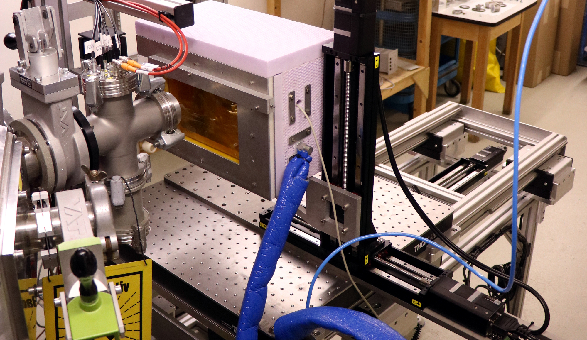
Overview of the irradiation site at the high current room of the Bonn Isochronus Cyclotron. The setup consists of a thermally-insulated cooling box on a two-dimensional motor stage which is mounted on a custom-made setup table. A liquid nitrogen reservoir is used to cool nitrogen gas which is guided into the cooling box. Shown is the setup in irradiation position, only several centimeters from the extraction window.
Proton Irradiation Characteristics (typical)
| Energy | \( 7~\text{to}~ 14~\text{MeV} ~~~(14~ \text{MeV})\) |
| Beam Current | \(20~ \text{nA}~\text{to}~ 2~ \mu\text{A} ~~~(1~ \mu\text{A})\) |
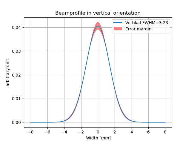
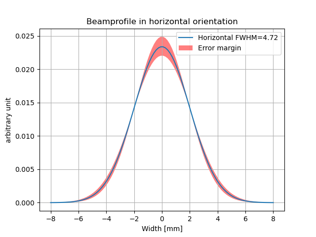
| Beam Width \((x/y)\) | \(\text{few mm}~~~ (4/6~\text{mm})\) |
| Temperature on DUT | \(\text{down to}~ -40~^\circ\text{C}~~~ (-20~^\circ\text{C})\) |
| Max. DUT Area | \(19~\text{cm} \times 11~\text{cm} ~~~(2~\text{cm} \times 1~\text{cm})\) |
| Max. DUT Thickness (Si) | \(300 ~\mu \text{m}~~~ (150~\mu \text{m})\) |
| Min. | Max. NIEL per Scan | \(\left.5\cdot 10^{11} ~~\right\arrowvert ~~10^{14} ~\text{ neq}/\text{cm}^2\) |
| NIEL/TID Ratio | \(10^{13}~ \text{ neq}/\text{cm}^2 \text{ per Mrad}\) |
Fluence Determination
The proton fluence \(\Phi_\text{P}\) is directly proportional to the NIEL damage. Knowing the proton beam current \( I_\text{P} \), the fluence is calculated by $$ \Phi_\text{P}=\frac{I_\text{P}}{q_\text{e}\cdot v_x\cdot \Delta y} $$ This equation describes the fluence per complete scan of the respective area, with the electric charge \(q_\text{e}\), the scan speed \(v_x\) and the vertical step size \(\Delta y\).
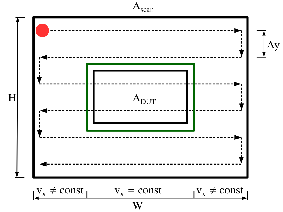
Shown is the the schematic scanning procedure, the beam spot (red circle) is moved in a grid over the scanned area, separated into \(H/\Delta y\) rows. The DUT is placed inside the green rectangle, where the scan speed (and therefore the fluence) is constant.
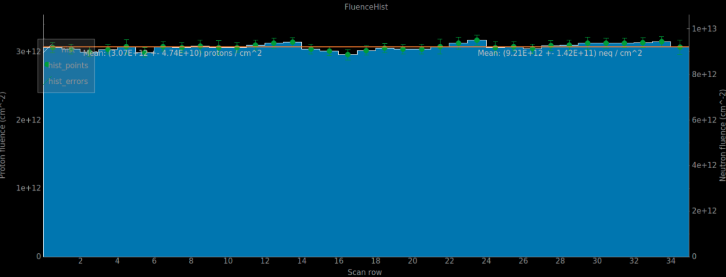
The beam current \(I_\text{P}\) is measured with 10 to 100 Hz within each scanned row whereas \(\Delta y\) and \(v_x\) are directly obtained from the motorstage. Below, the fluence distripution on the scan area is shown with row-resoltution. The proton fluence is indicated on the first, the neutron fluence on the second y-axis. The average fluence over the entire scan area is given by the horizontal line.
Proton Hardness Factor
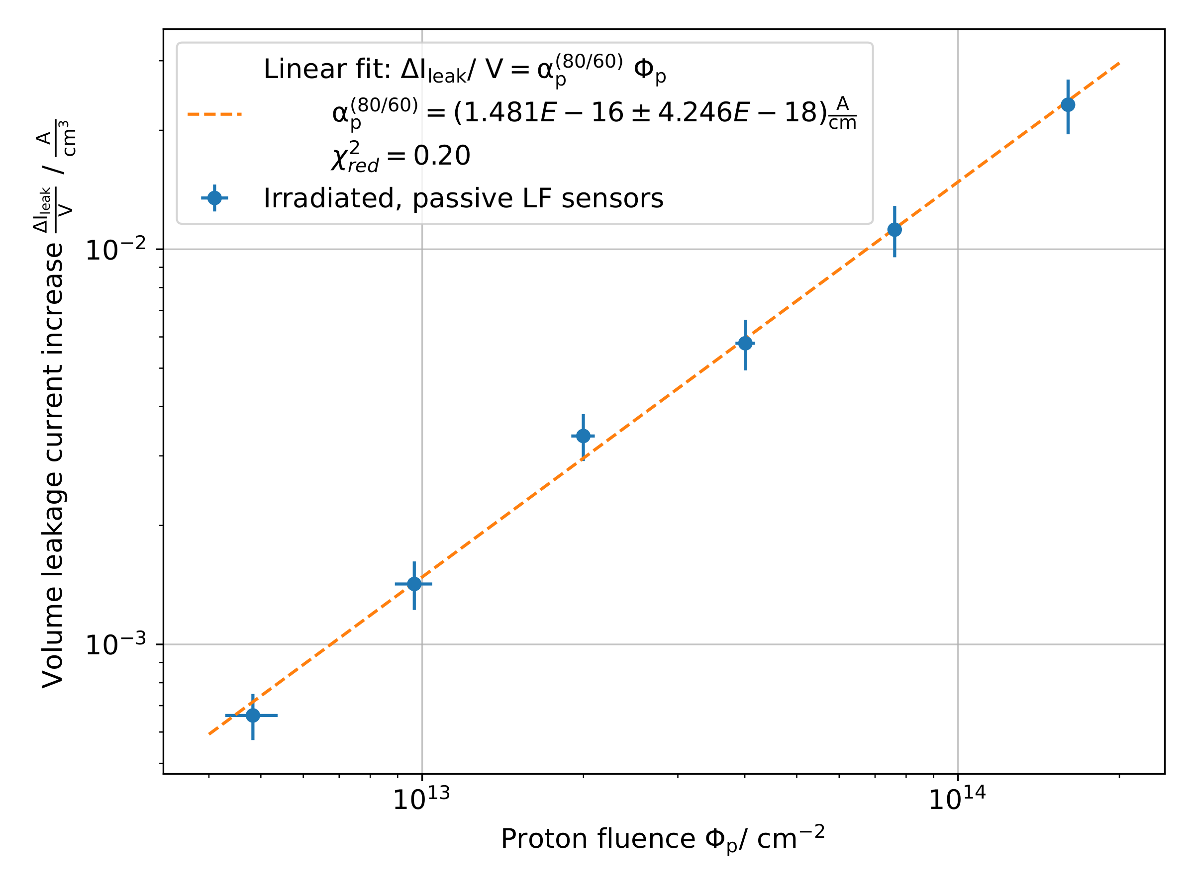
For 13.5 MeV protons (~ 12.28 MeV on DUT) a hardness factor of $$ \kappa_p = 3.71 \pm 0.11 $$ was determined using six irradiated 150 μm LFoundry test structures.
Beam Diagnostics
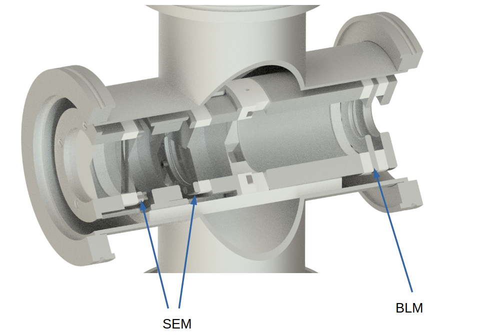
In order to determine the beam current, relative position and possible beam cut-off at extraction, a custom-made, calibrated beam monitor as well as readout board is used. The beam monitor consist of a secondar-electron monitor (SEM) as well as beam-loss monitor (BLM) modules. The SEM module consists of 2 pairs of segmented (horizontal / vertical respectively), thin, aluminium foils, which are penetrated by the beam. On penetration, the beam knocks secondary electrons off the foil surfaces which are collected via electrodes. The sum of all foils is directly proportional to the beam current and allows for non-destructive beam current measurement after calibration. The ratio between the foil signals allows for relative beam position determination. The BLM module consists of a aperture of the same size as the extraction window. When the beam is (purposly) deflected onto the BLM, the beam loss can be measured directly.
After passing the beam monitor, the beam exits the vacuum and is transmitted to the DUT inside the cooling box.
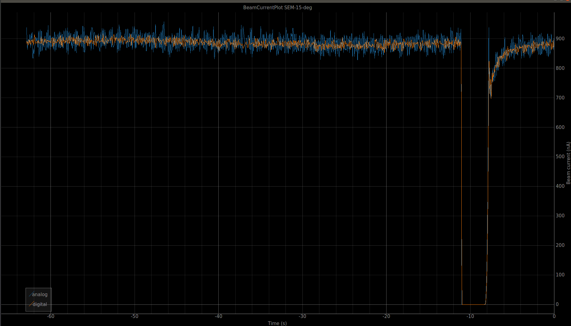
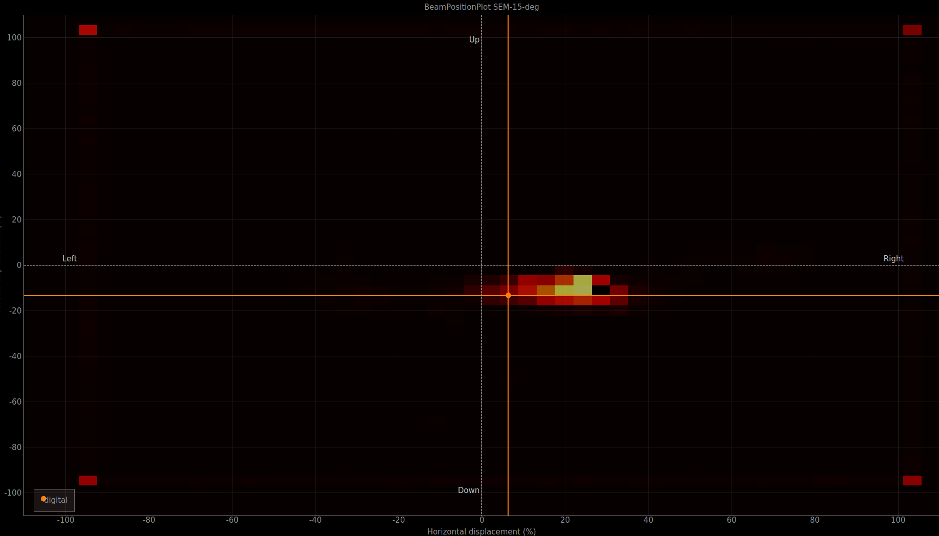
Shown are the visualizations of beam data, available in the online monitor tab of the irrad_control GUI using the installed SEM. The first figure shows the beam current over time while the no beam is extracted. The second figure shows the relative beam position at the location of the SEM.
User
The setup described is available to internal and external research groups. For external groups, its use is regulated by a cooperation agreement. For further information regarding the utilization of the irradiation setup, please use the contact.
Publications
P. Wolf, "Development and Characterization of an Irradiation Site for Radiation Damage Studies of the ATLAS ITk Pixel Detector", PhD-Thesis, Silab (AG Prof. J. Dingfelder), Physikalisches Institut, University of Bonn, June 2025, doi:10.48565/bonndoc-609
P. Wolf, D. Sauerland, R. Beck and J. Dingfelder, "A beam-driven proton irradiation setup for precision radiation damage tests of silicon detectors", in Nuclear Instruments and Methods in Physics Research Section A: Accelerators, Spectrometers, Detectors and Associated Equipment, Vol. 1064, Apr. 2024, doi:10.1016/j.nima.2024.169358 (Poster)
D. Sauerland, R. Beck, J. Dingfelder, P.D. Eversheim and P. Wolf, "Proton Irradiation Site for High-Uniformity Radiation Hardness Tests of Silicon Detectors at the Bonn Isochronous Cyclotron", in Proc. Cyclotrons'22, Beijing, China, Dec. 2022, pp. 38-41. doi:10.18429/JACoW-CYCLOTRONS2022-MOBO03 (Contributed Talk)
D. Sauerland, R. Beck, J. Dingfelder, P.D. Eversheim, and P. Wolf, “Proton Irradiation Site for Si-Detectors at the Bonn Isochronous Cyclotron”, in Proc. IPAC'22, Bangkok, Thailand, Jun. 2022, pp. 130-132. doi:10.18429/JACoW-IPAC2022-MOPOST030 (Poster)
![]()